




EXECUTIVE SUMMARY: INTEGRATED URBAN FLOOD RESILIENCE ENGINEERING FRAMEWORK FOR GHANA
1. Background
Urban flooding has become one of the most significant threats to Ghana's urban development, public safety, infrastructure resilience, and economic sustainability. Over the past several decades, rapid urbanisation, increasing land-use intensity, expansion of impervious surfaces, encroachment upon natural waterways, inadequate spatial planning, and changing rainfall characteristics have combined to increase both the frequency and severity of flood events in many parts of the country. Metropolitan areas such as Accra, Kumasi, Sekondi-Takoradi, Cape Coast, Tema, and several rapidly expanding municipalities continue to experience recurring flood disasters that result in loss of life, destruction of homes and businesses, interruption of transportation systems, damage to public utilities, environmental degradation, and substantial economic losses.
Successive governments have invested considerable resources in drainage construction, rehabilitation of stormwater infrastructure, desilting programmes, emergency relief operations, public education campaigns, and enforcement exercises against illegal developments within waterways. These interventions remain necessary and have reduced flood impacts in some locations. Nevertheless, the persistence of severe flooding demonstrates that conventional responses, although valuable, have not fully addressed the broader engineering and systems challenges that influence urban flood behaviour.
This White Paper argues that the continued recurrence of flooding is not solely the consequence of inadequate drainage capacity. Rather, it reflects the interaction of hydrological processes, hydraulic constraints, geotechnical conditions, spatial planning deficiencies, land development practices, fragmented institutional responsibilities, and parcel-level engineering decisions. Consequently, sustainable flood resilience cannot be achieved through isolated infrastructure projects alone. It requires an integrated engineering framework that manages stormwater as a continuous hydraulic system extending from individual properties to its final receiving environment.
2. Engineering Problem Statement
Traditional urban flood management has generally concentrated on increasing the capacity of drainage channels, constructing culverts, widening waterways, and undertaking periodic maintenance. While these interventions are essential components of flood management, they frequently address only the downstream symptoms of a much larger hydraulic system.
Stormwater behaviour is influenced long before it reaches a primary drain. Decisions made at the scale of individual developments—including boundary wall construction, site grading, building orientation, surface paving, property enclosure, and preservation or obstruction of natural overland flow paths—collectively determine how water enters, moves through, and exits the urban environment.
Where numerous properties impede the natural movement of floodwater, runoff accumulates within enclosed compounds, spills unpredictably onto roads, overloads local drainage infrastructure, and contributes to widespread flooding beyond the point where the obstruction originally occurred. In this respect, urban flooding represents the cumulative behaviour of an interconnected hydraulic network rather than the isolated failure of individual drainage structures.
The engineering challenge is therefore broader than enlarging drains. It is to ensure that rainfall can move safely, continuously, and predictably through the entire urban landscape under both ordinary and extreme storm conditions.
3. Central Proposition of the White Paper
This White Paper proposes a transition from conventional drainage-centred flood management toward an integrated urban hydraulic systems approach.
The central proposition is that urban flood resilience should be engineered as a connected hydraulic system extending from individual parcels to the final receiving water body. Every component of the urban environment—including private developments, neighbourhood layouts, drainage infrastructure, open spaces, flood storage areas, rivers, wetlands, and coastal outlets—should be planned and managed as interconnected elements of a single hydraulic network.
Accordingly, the framework I developed in this White Paper introduces a systems-based approach that integrates hydrological science, hydraulic engineering, geotechnical engineering, urban and regional planning, environmental management, and infrastructure governance into a coordinated strategy for reducing flood risk.
Rather than seeking to eliminate flooding—an objective that is neither technically realistic nor economically feasible under extreme rainfall conditions—the framework seeks to modify flood behaviour. Its objective is to reduce the depth, duration, velocity, and destructive consequences of floodwaters by improving the continuity, efficiency, and resilience of the urban hydraulic system.
This systems perspective recognises that successful flood management depends not only on the capacity of primary drains but also on preserving hydraulic continuity across every stage of stormwater movement, from rainfall interception at the parcel level to controlled discharge into rivers, streams, wetlands, reservoirs, lagoons, and the sea.
The framework therefore promotes coordinated engineering design, informed spatial planning, and evidence-based policy as the foundation for long-term urban flood resilience in Ghana.
4. The Integrated Urban Flood Resilience Engineering Framework
The principal contribution of this White Paper is the development of an integrated engineering framework for managing urban flooding as a continuous hydraulic system rather than as a series of isolated drainage problems. The framework recognises that flood behaviour is governed by interactions between hydrological processes, hydraulic pathways, land-use patterns, geotechnical conditions, urban development practices, and infrastructure performance. Consequently, effective flood resilience requires coordinated interventions at multiple spatial scales instead of reliance on individual engineering measures.
The framework is built upon four complementary engineering components that operate together to improve the movement, storage, and controlled discharge of stormwater throughout the urban environment.
4.1 Parcel Hydraulic Permeability (PHP)
The first component of the framework is Parcel Hydraulic Permeability (PHP).
This White Paper introduces Parcel Hydraulic Permeability as a proposed engineering concept describing the ability of an individual property to permit the controlled movement of floodwater across its boundaries without creating unnecessary hydraulic obstruction.
In many urban communities, particularly within flood-prone areas, perimeter walls constructed from continuous reinforced concrete create enclosed compounds that significantly restrict overland flow. During intense rainfall, runoff entering these compounds may become temporarily impounded until water levels rise sufficiently to overtop the walls or enter buildings through gates, doors, windows, or other openings.
The framework proposes that, where appropriate and supported by engineering assessment, developments located within designated flood-prone zones should minimise unnecessary hydraulic barriers while maintaining adequate security, privacy, and structural integrity. This objective may be achieved through alternative boundary treatments, engineered flood-relief openings, permeable fencing systems, or other technically suitable solutions that allow controlled passage of floodwater.
The objective is not to increase flooding within communities but to reduce artificial ponding and shorten the residence time of floodwater by allowing runoff to continue moving toward designated drainage pathways.
Accordingly, Parcel Hydraulic Permeability should be regarded as one element of an integrated flood resilience strategy and not as an independent solution to urban flooding.
4.2 Urban Hydraulic Connectivity (UHC)
The second component of the framework is Urban Hydraulic Connectivity (UHC).
Urban Hydraulic Connectivity describes the degree to which stormwater can move continuously through the built environment without interruption caused by physical obstructions, disconnected drainage systems, incompatible infrastructure, or fragmented land development.
Hydraulic connectivity extends beyond engineered drains. It includes the relationship between individual parcels, roads, open spaces, neighbourhood drainage systems, secondary channels, primary drains, wetlands, floodplains, rivers, and coastal discharge points.
Where this connectivity is interrupted, runoff accumulates, hydraulic pressure increases, drainage systems surcharge, and floodwaters are diverted into locations not originally intended to receive them. Conversely, where hydraulic continuity is maintained, stormwater is conveyed more efficiently, reducing localised ponding and improving overall system performance.
This White Paper therefore proposes that hydraulic connectivity should become a fundamental consideration in urban planning, engineering design, and infrastructure regulation.
4.3 Flood Conveyance Corridors (FCC)
The third component of the framework is Flood Conveyance Corridors (FCC).
Flood Conveyance Corridors are designated and protected pathways intended to safely transport excess stormwater from urban areas toward suitable receiving environments during periods of intense rainfall.
These corridors may consist of natural waterways, engineered drainage channels, floodways, protected green corridors, widened drainage reserves, or appropriately designed open spaces that collectively maintain uninterrupted flood conveyance.
An effective Flood Conveyance Corridor should satisfy several engineering objectives:
- maintain sufficient hydraulic capacity during design storm events;
- minimise flow obstruction caused by encroachment or incompatible development;
- remain connected to secondary and primary drainage systems;
- reduce hydraulic backwater effects;
- facilitate routine maintenance and inspection; and
- safely discharge stormwater into designated receiving environments.
Protection of these corridors should be incorporated into urban planning policies and supported by appropriate development controls.
4.4 Urban Flood Storage Management (UFSM)
The fourth component is Urban Flood Storage Management (UFSM).
Even where drainage systems function efficiently, extreme rainfall events may generate runoff volumes that temporarily exceed conveyance capacity. Under such conditions, controlled temporary storage becomes an essential component of flood resilience.
Urban Flood Storage Management promotes the planned use of detention basins, retention ponds, restored wetlands, floodplains, recreational open spaces, and other engineered or natural storage facilities capable of temporarily retaining excess runoff before gradually releasing it into downstream drainage systems.
By reducing peak discharge rates, distributed storage systems lessen hydraulic stress on drainage infrastructure, decrease downstream flood peaks, and improve overall network resilience.
UFSM therefore complements drainage expansion by addressing one of the principal causes of urban flooding—the mismatch between peak runoff generation and available conveyance capacity.
4.5 Integration of the Framework
The effectiveness of the proposed framework does not depend upon any single component. Rather, its strength lies in the coordinated interaction of all four elements.
Parcel Hydraulic Permeability reduces unnecessary obstruction at the property level.
Urban Hydraulic Connectivity ensures that runoff moves continuously across neighbourhoods and infrastructure networks.
Flood Conveyance Corridors provide protected pathways for high-volume stormwater movement.
Urban Flood Storage Management moderates peak flows through controlled temporary retention.
Together, these components establish an integrated urban hydraulic system that seeks to manage flood behaviour from the point where rainfall reaches the ground until it is safely discharged into rivers, streams, wetlands, reservoirs, lagoons, or the sea.
This integrated systems philosophy represents the central engineering contribution of the White Paper and forms the foundation upon which the subsequent policy proposals, planning recommendations, engineering metrics, and implementation strategies are developed.
5. Proposed Engineering Policy and Regulatory Framework
The effectiveness of engineering solutions depends not only on sound technical design but also on the regulatory environment within which they are implemented. Engineering innovations that are not supported by planning regulations, development control, and institutional enforcement frequently achieve only limited success. Consequently, this White Paper proposes complementary policy instruments to facilitate the practical implementation of the Integrated Urban Flood Resilience Engineering Framework.
The objective of these policy proposals is to strengthen the relationship between engineering practice, urban planning, hydrological management, and development regulation by introducing measurable standards that improve hydraulic performance at both the parcel and city scales.
5.1 Proposed Urban Hydraulic Management Zones (UHMZ)
This White Paper proposes the establishment of a new planning and engineering zoning classification known as Urban Hydraulic Management Zones (UHMZs).
Urban Hydraulic Management Zones are designated flood-prone areas where additional engineering and development requirements would apply because of their importance to stormwater movement, flood storage, or hydraulic connectivity. These zones would not replace existing land-use classifications but would operate as an additional engineering overlay within planning and development control systems.
The purpose of UHMZs is to preserve and enhance the hydraulic performance of urban environments by reducing unnecessary flow obstructions and maintaining continuous stormwater pathways during both ordinary and extreme rainfall events.
Within designated Urban Hydraulic Management Zones, planning authorities may consider introducing engineering requirements such as:
- limiting the construction of solid concrete perimeter walls above specified heights where they are demonstrated to obstruct flood movement;
- encouraging perimeter enclosures that maintain defined levels of hydraulic permeability while preserving security and privacy;
- requiring entrance gates to incorporate engineered flood-relief openings or other approved hydraulic relief features where appropriate;
- protecting existing natural overland flow paths and preventing their obstruction during new developments;
- requiring flood-flow impact assessments as part of planning approval for developments located within identified flood-prone areas;
- preserving access corridors for inspection, maintenance, and emergency flood management operations; and
- integrating flood resilience considerations into subdivision design, road layouts, drainage planning, and public open-space development.
The precise engineering standards applicable within UHMZs should be determined through detailed hydraulic studies, local flood modelling, stakeholder consultation, and statutory planning processes. The recommendations contained in this White Paper are therefore presented as policy proposals intended for technical evaluation rather than immediate regulatory standards.
5.2 Parcel Hydraulic Permeability Index (PHPI)
To support objective engineering assessment, this White Paper proposes a new engineering performance indicator known as the Parcel Hydraulic Permeability Index (PHPI).
The PHPI is intended to provide planners, engineers, architects, surveyors, and development control authorities with a measurable indicator of the extent to which an individual property permits the controlled movement of floodwater across its boundaries.
Unlike traditional planning assessments that primarily evaluate structural development, the PHPI focuses specifically on the hydraulic behaviour of parcel boundaries during flood events.
Illustrative values may include:
| Boundary Type | Illustrative PHPI |
| Solid reinforced concrete wall | 0% |
| Decorative block wall with limited openings | 20% |
| Perforated masonry wall | 50% |
| Steel mesh or engineered permeable fence | 90–95% |
These values are illustrative only and should be calibrated through hydraulic experiments, computational modelling, and field observations before incorporation into engineering standards or building regulations.
The PHPI is not intended to prescribe a single construction method. Rather, it establishes a performance-based approach in which different engineering solutions may be adopted, provided they achieve acceptable hydraulic permeability while satisfying structural, architectural, security, and public safety requirements.
5.3 Hydraulic Connectivity Hierarchy (HCH)
A central principle of this framework is the establishment of a Hydraulic Connectivity Hierarchy (HCH).
The Hydraulic Connectivity Hierarchy recognises that successful flood management depends upon uninterrupted hydraulic linkage from the point where rainfall reaches the ground to its final receiving environment. Every component of the drainage network should therefore be designed as part of a continuous hydraulic sequence.
The proposed hierarchy is as follows:
Rainfall
↓
Parcel Surface Drainage
↓
Parcel Hydraulic Permeability (PHP)
↓
Inter-Property Flow Paths
↓
Local Street Drainage
↓
Secondary Link Channels
↓
Primary Drainage Channels
↓
Flood Conveyance Corridors (FCC)
↓
Urban Flood Storage Management Systems (UFSM)
↓
Receiving Water Bodies (Rivers, Streams, Wetlands, Reservoirs, Lagoons, and the Sea)
The efficiency of the entire hydraulic system depends upon maintaining continuity throughout this sequence. A failure or obstruction at any level can reduce the performance of downstream infrastructure, increase local flood depths, generate hydraulic backwater effects, and transfer flood risk to adjacent communities.
Accordingly, engineering design, maintenance programmes, urban planning decisions, and infrastructure investments should be evaluated not only on the basis of individual assets but also on their contribution to the continuity of the complete hydraulic network.
5.4 Integrated Regulatory Approach
The proposals presented in this chapter are intended to complement, rather than replace, existing drainage engineering practices and planning regulations.
The White Paper does not suggest that permeable property boundaries, Urban Hydraulic Management Zones, or the Parcel Hydraulic Permeability Index alone will eliminate urban flooding. Instead, these measures are proposed as components of a broader flood resilience strategy that also includes:
- expansion and rehabilitation of primary and secondary drainage infrastructure;
- routine maintenance and desilting of drainage systems;
- protection and restoration of wetlands and natural floodplains;
- construction of detention and retention facilities;
- improved spatial planning and development control;
- climate adaptation measures;
- watershed management; and
- continuous hydrological monitoring and engineering assessment.
When implemented as an integrated system, these complementary interventions have the potential to improve urban hydraulic performance, reduce flood depth and duration, minimise damage to infrastructure, and strengthen the resilience of Ghana's rapidly growing urban centres.
5.5 Chapter Summary
This chapter has proposed three complementary policy and engineering innovations to support implementation of the Integrated Urban Flood Resilience Engineering Framework:
- Urban Hydraulic Management Zones (UHMZs) as a planning and regulatory overlay for flood-prone areas.
- Parcel Hydraulic Permeability Index (PHPI) as a measurable engineering indicator for assessing the hydraulic performance of individual developments.
- Hydraulic Connectivity Hierarchy (HCH) as a systems engineering principle linking rainfall, parcel design, drainage infrastructure, flood conveyance, flood storage, and final discharge into receiving water bodies.
Together, these proposals provide practical mechanisms through which engineering design, urban planning, and public policy may be better aligned to improve long-term flood resilience. Their adoption should be supported by detailed hydraulic modelling, pilot implementation projects, stakeholder engagement, and periodic technical review before incorporation into national engineering standards.
6. Scientific and Engineering Basis of the Framework
The Integrated Urban Flood Resilience Engineering Framework is founded upon established principles of hydrology, hydraulic engineering, geotechnical engineering, urban and regional planning, systems engineering, environmental management, and climate adaptation. Rather than replacing existing engineering practice, the framework seeks to improve the performance of current flood management systems through better integration, coordination, and regulation across multiple spatial and institutional scales.
The framework recognises that urban flooding results from the interaction of three principal factors:
- the generation of runoff through rainfall and catchment response;
- the movement of stormwater through the built environment; and
- the capacity of natural and engineered systems to convey, temporarily store, and safely discharge excess water.
Where any one of these processes is disrupted, the performance of the entire hydraulic system is affected. Flooding therefore becomes an emergent systems problem rather than the isolated failure of a single drain, culvert, or channel.
The engineering philosophy advanced in this White Paper is that every component of the urban landscape—including private developments, public infrastructure, drainage networks, floodplains, wetlands, and receiving water bodies—forms part of an interconnected hydraulic system. Consequently, engineering decisions made at the parcel level can influence flood behaviour at the neighbourhood, municipal, and catchment scales.
The proposed concepts of Parcel Hydraulic Permeability (PHP), Urban Hydraulic Connectivity (UHC), Flood Conveyance Corridors (FCC), Urban Flood Storage Management (UFSM), Urban Hydraulic Management Zones (UHMZ), the Parcel Hydraulic Permeability Index (PHPI), and the Hydraulic Connectivity Hierarchy (HCH) are presented as complementary tools within this integrated systems approach. Their application should be informed by detailed hydrological investigations, hydraulic modelling, geotechnical assessments, environmental impact studies, and local planning considerations.
Importantly, the framework does not advocate a single engineering solution. Instead, it promotes a performance-based approach in which different technical solutions may be adopted provided they collectively improve hydraulic continuity, reduce flood risk, and strengthen long-term urban resilience.
7. Expected Engineering, Environmental, Social, and Economic Benefits
If progressively implemented and validated through pilot projects, the proposed framework has the potential to generate significant benefits across multiple sectors.
Engineering Benefits
From an engineering perspective, the framework seeks to:
- improve hydraulic continuity throughout urban drainage systems;
- reduce artificial obstructions to stormwater movement;
- moderate peak runoff entering drainage infrastructure;
- improve the operational performance of existing drainage networks;
- reduce localised ponding and prolonged inundation; and
- support more resilient infrastructure planning under changing climatic conditions.
These improvements are expected to complement ongoing investments in drainage expansion, rehabilitation, and maintenance.
Environmental Benefits
Improved management of stormwater can contribute to broader environmental objectives by:
- protecting natural waterways from excessive erosion;
- reducing uncontrolled sediment transport;
- preserving wetlands and natural floodplains;
- encouraging nature-based flood management where appropriate;
- improving groundwater recharge opportunities in suitable locations; and
- supporting integrated watershed management.
Environmental protection should be regarded as an essential component of flood resilience rather than an independent objective.
Social Benefits
Flood disasters have substantial human consequences. Reducing flood impacts can contribute to:
- improved public safety;
- protection of residential communities;
- reduced displacement of households;
- improved access to schools, healthcare facilities, and workplaces during rainfall events;
- greater confidence in urban development; and
- enhanced quality of life for residents of flood-prone communities.
A more resilient urban environment also strengthens public confidence in planning institutions and engineering infrastructure.
Economic Benefits
Urban flooding imposes direct and indirect economic costs through infrastructure damage, business interruption, property losses, emergency response, environmental remediation, and reduced productivity.
An integrated flood resilience strategy has the potential to:
- reduce recurrent infrastructure repair costs;
- improve the lifespan of public drainage assets;
- minimise disruption to transportation networks;
- reduce emergency response expenditure;
- improve investor confidence in urban development; and
- support long-term economic resilience through better infrastructure performance.
Although implementation will require investment, preventive engineering measures are generally more cost-effective over the long term than repeated post-disaster reconstruction.
8. National Implementation Strategy
Successful implementation of the Integrated Urban Flood Resilience Engineering Framework should be progressive, evidence-based, and coordinated across multiple institutions. A phased implementation strategy is recommended to minimise risk, allow technical refinement, and ensure that regulatory reforms are informed by practical experience.
Phase I – National Assessment and Mapping
The first phase should focus on developing a comprehensive understanding of existing flood conditions through:
- high-resolution flood hazard mapping;
- identification of natural drainage pathways;
- delineation of floodplains and flood-prone communities;
- assessment of drainage network performance;
- inventory of hydraulic obstructions; and
- identification of candidate Urban Hydraulic Management Zones.
This phase should establish the technical baseline upon which future engineering interventions are designed.
Phase II – Pilot Projects and Technical Validation
Pilot projects should be undertaken within selected urban catchments representing different development patterns and flood characteristics.
These pilots should evaluate:
- the practical application of Parcel Hydraulic Permeability measures;
- establishment of Urban Hydraulic Management Zones;
- calibration of the Parcel Hydraulic Permeability Index;
- improvement of hydraulic connectivity;
- effectiveness of Flood Conveyance Corridors; and
- performance of Urban Flood Storage Management systems.
Results from pilot projects should inform future regulatory development and engineering standards.
Phase III – Regulatory Integration
Following successful pilot evaluation, relevant planning and engineering regulations should be reviewed to incorporate validated elements of the framework.
Potential areas for integration include:
- planning approval procedures;
- subdivision regulations;
- engineering design guidelines;
- building permit requirements;
- flood impact assessment procedures; and
- municipal infrastructure planning.
Implementation should be accompanied by training programmes for engineers, planners, surveyors, architects, building inspectors, and development control officers.
Phase IV – National Rollout and Continuous Improvement
The final phase should involve progressive implementation across metropolitan, municipal, and district assemblies, supported by continuous monitoring, periodic technical review, updated hydrological data, and ongoing refinement of engineering standards.
Flood resilience should be treated as a dynamic process requiring regular adaptation to changing climatic conditions, urban growth, technological advancement, and emerging scientific knowledge.
The long-term success of the framework will depend upon sustained institutional collaboration, adequate investment, public awareness, effective maintenance, and continuous engineering innovation.
CHAPTER 1 — THE FLOODING PROBLEM, WHY PAST RESPONSES HAVE FALLEN SHORT, AND WHAT ENGINEERING ACTUALLY EXPLAINS
Ghana’s urban flood challenge is increasingly recognised as an infrastructure and land-management problem rather than only a climatic hazard. The Ghana Hydrological Authority identifies drainage planning, design, supervision, and maintenance of stormwater systems as critical components of national flood-risk reduction. This reinforces the principle that resilient urban flood management requires integrated drainage engineering, spatial planning, and maintenance systems rather than isolated emergency responses.
Flooding in Ghana's cities is not a mystery, and this paper does not treat it as one. Accra, Kumasi, Sekondi-Takoradi, Tema, Kasoa, Tamale, and a growing list of municipalities experience recurring flood events that cost lives, destroy property, interrupt transport and commerce, and impose recurring reconstruction costs on the state. Rapid urbanisation, the expansion of impervious surfaces, encroachment on natural waterways, weak enforcement of planning regulations, and a changing rainfall regime under climate change have combined to make this worse over time, not better.
Successive governments have responded with drainage expansion, dredging, desilting, and emergency response — and these measures have helped in specific locations. But the persistence of severe flooding despite this investment tells us something specific: that conventional drainage-capacity thinking, while necessary, is treating a symptom rather than the full system. Three structural reasons explain why.
-
- Drainage Expansion Alone Cannot Outrun Urbanisation
Every hectare of new impervious surface — rooftops, paved compounds, roads — converts what used to be gradual infiltration into rapid, concentrated runoff. Drainage networks sized for yesterday's land cover are structurally undersized for today's, even before rainfall intensity is considered. Expanding drains is necessary, but it is chasing a moving target as long as the urbanisation that drives runoff continues unmanaged upstream of the drain.
1.2 Maintenance Cannot Keep Pace with Sediment and Solid Waste
Even a correctly sized drain loses hydraulic capacity rapidly under sediment accumulation, vegetation growth, and solid waste dumping — a chronic and well-documented condition across Ghanaian urban drainage networks. A conveyance system's theoretical capacity and its actual, as-maintained capacity are often two very different numbers.
1.3 Conventional Measures Address Conveyance, Not the Generation and Routing of Runoff
Drainage engineering has historically focused on moving water that has already accumulated. It pays comparatively little attention to the parcel- and neighbourhood-scale decisions — boundary construction, site grading, building orientation — that determine how much runoff is generated, where it accumulates first, and whether it reaches the drainage network in a smooth, distributed way or as a sudden concentrated surge. This is the gap this paper is written to address.
1.4 The Essential Hydraulics, Briefly
Two hydraulic ideas matter for everything that follows, and both are standard, uncontested engineering principles — stated here briefly because the argument that follows depends on them, not to re-teach open-channel hydraulics from first principles.
- Runoff generation and routing: rainfall that cannot infiltrate becomes surface runoff; how quickly and how directly that runoff reaches a conveyance channel determines peak flow rate and, therefore, flood depth. A catchment that releases the same total rainfall volume gradually and continuously floods less severely than one that releases it suddenly and simultaneously, even though the total volume is identical.
- Hydrostatic pressure and impoundment: any barrier that fully blocks the movement of water on one side while water continues to accumulate creates a pressure differential across that barrier. This is the same principle that governs retaining-wall drainage design, flood-wall design, and — as this paper argues — the behaviour of solid compound walls in flood-prone residential layouts.
The application of international flood-resilience principles to Ghana requires grounding within verified national hydrometeorological and disaster-risk evidence. Ghana’s flood vulnerability is not a theoretical projection but a documented national risk pattern supported by disaster records, rainfall analysis, and infrastructure planning data.
Ghana-Specific Evidence Base: Flood Exposure, Rainfall Extremes and Urban Vulnerability
The National Disaster Management Organisation (NADMO) identifies recurrent flooding as a major national hazard affecting both urban and rural settlements. Historical flood records show significant events including the 2015 June 3 Accra flood disaster, which resulted in extensive loss of lives and property, as well as major flood episodes associated with dam releases and extreme rainfall events. NADMO’s flood disaster profile further identifies Greater Accra, Central, and Volta Regions as among the areas experiencing repeated urban and coastal flooding pressures.
The hydrological basis for flood risk assessment in Ghana is also supported by locally developed rainfall intensity analysis. The Ghana Meteorological Agency (GMet) produces Intensity-Duration-Frequency (IDF) rainfall products derived from historical rainfall observations collected through Ghana’s meteorological station network. These datasets provide the statistical relationship between rainfall intensity, duration, and recurrence intervals required for stormwater drainage design and flood-control infrastructure planning.
Research using Ghana Meteorological Agency rainfall records has specifically developed short-duration rainfall intensity-frequency curves for the Greater Accra Region. Using rainfall data from four meteorological stations within Greater Accra, the study analysed return periods ranging from 2 to 100 years and demonstrated the importance of locally calibrated rainfall parameters for urban drainage and hydraulic infrastructure design.
Therefore, the vulnerability of flood-prone compounds in Ghana should be understood as the interaction of three measurable conditions: (1) exposure to intense rainfall events, (2) settlement expansion into flood-sensitive areas, and (3) limitations in stormwater conveyance capacity. The Ghana evidence base confirms that flood risk is not solely a consequence of rainfall magnitude but a systems failure involving land-use planning, drainage capacity, maintenance practices, and enforcement mechanisms.
Table: Ghana Flood Risk Evidence Sources
| Evidence Area | Ghana Source | Contribution to Paper |
| Historical flood disasters | NADMO Flood Disaster Profile | Establishes national flood recurrence and affected regions |
| Rainfall intensity thresholds | Ghana Meteorological Agency IDF Product | Provides engineering basis for drainage and flood modelling |
| Greater Accra rainfall modelling | Logah, Kankam-Yeboah & Bekoe (2013), CSIR repository | Provides local rainfall-frequency analysis |
| Drainage infrastructure governance | Ghana Hydrological Authority Drainage Unit | Supports discussion on stormwater management responsibilities |
Source: NADMO – Flood Disaster profile - Ghana.
Climate change adds a further layer of urgency rather than a new mechanism: historical rainfall records, which most existing drainage design still relies on, are becoming a progressively less reliable guide to future storm intensity. Infrastructure and regulation built only to historical assumptions carries a widening margin of under-design that grows every year it is not revisited.
The remainder of this paper does not attempt to re-argue the case that flooding is a serious national problem — that much is not in dispute. It focuses entirely on the specific, under-examined mechanism at parcel scale, and on what would need to be true for an engineering intervention at that scale to actually work.
CHAPTER 2 — THE HIDDEN ENGINEERING PROBLEM: WHEN A COMPOUND WALL BECOMES A RESERVOIR
The central and most original claim of this paper is narrow and specific: in flood-prone Ghanaian residential layouts, a continuous, impermeable perimeter wall can function, hydraulically, as a small reservoir wall around the property it is meant to protect — accumulating water against the very structure it was built to defend, rather than keeping water out.
That claim is correct often enough to matter. But it is not correct universally, and treating it as universal is the single biggest weakness in earlier drafts of this framework. There are two physically distinct mechanisms by which a compound wall interacts with floodwater, and they call for different, sometimes opposite, engineering responses.
2.1 Mechanism A — External Floodwater Entering an Enclosed Compound
Where a property sits on the downstream or lower-lying side of a poorly graded street, rising street-level floodwater can enter the compound over a low threshold or through a gate, after which a solid perimeter wall prevents that water from draining back out as the street level falls. The compound holds a flood level for longer than the street does. This is the scenario most people picture when they describe compound walls trapping floodwater, and it is real.
2.2 Mechanism B — The Compound's Own Rainfall and Runoff, Trapped by Its Own Boundary
A second, and in many flat, poorly graded Ghanaian residential layouts probably more common, mechanism has nothing to do with the street. Rain falling directly on the roof and courtyard of the property itself has nowhere to go, because the same solid wall built to keep street floodwater out also has no low-level opening to let the compound's own runoff out. The gate threshold, deliberately raised for exactly this security purpose, becomes an unintended dam against the property's own rainfall.
This distinction is not academic. It determines which fix is appropriate, and the wrong choice actively makes things worse:
- Where Mechanism B dominates — the compound is mainly flooding from its own rainfall — a permeable boundary or a small number of engineered low-level openings solves the actual problem directly.
- Where Mechanism A dominates — the compound sits downstream and receives incoming street floodwater — a solid wall is doing useful work as a flood barrier. Replacing it with a permeable boundary removes that protection and can increase the property's flood exposure, not reduce it, unless the finished floor level is also raised above the design flood elevation.
Figure 3 illustrates this with a simple, non-site-specific layout: compounds on the higher, upstream side of a street mainly need help releasing their own trapped runoff (Mechanism B); compounds on the lower, downstream side are, in effect, receiving the neighbourhood's water and may be relying on their solid wall as protection (Mechanism A).
Figure 3. Illustrative plan view showing why boundary treatment must be assessed per site, not applied as a blanket rule. Schematic only — not a survey of any real community.
2.3 What This Means for the Rest of the Paper
Every subsequent recommendation in this paper is conditional on first establishing, site by site, which mechanism is dominant. This is not a hydraulic-modelling exercise — it is an observable, checkable fact about a property's siting, ground elevation relative to the street, and drainage layout, and it should be the first step of any pilot assessment under this framework, well before any wall is modified.
CHAPTER 3 — ENGINEERING RESPONSE: PERMEABLE BOUNDARIES AND ENGINEERED FLOOD VENTS
Having separated the two mechanisms, this chapter sets out two different engineering responses — not one universal solution — and is explicit about the practical obstacles each one faces.
3.1 Full Boundary Permeability — Wire-Mesh Fence-Walls
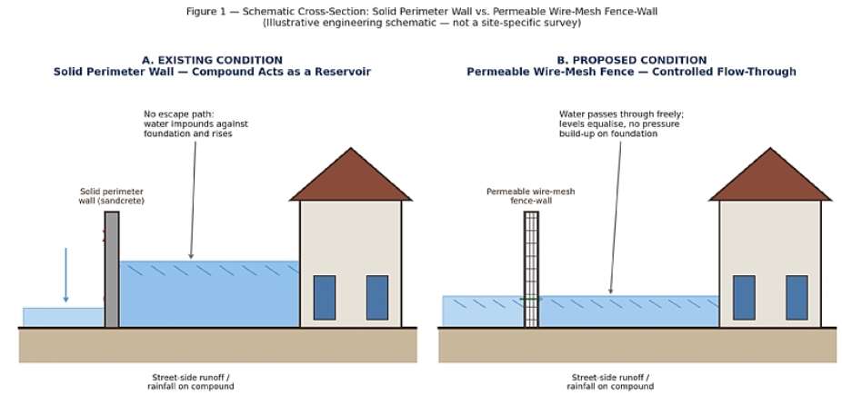
Where Mechanism B is dominant and the site is not required to act as a flood barrier against incoming street water, replacing a solid perimeter wall with a permeable wire-mesh fence allows the compound's own runoff to pass through freely in both directions, preventing the pressure differential and prolonged impoundment described in Chapter 2. Figure 1 shows the difference schematically.
Figure 1. Schematic cross-section comparing a solid perimeter wall (left), where floodwater impounds against the foundation with no escape path, and a permeable wire-mesh fence-wall (right), where water levels equalise and pass through freely. Illustrative only.
This option has three practical weaknesses that earlier drafts of this framework did not stress-test, and any pilot project must design around them rather than assume them away:
- Clogging under load. Ghanaian urban floodwater carries sediment, plastic waste, and vegetation debris, typically at the exact moment of peak flow. A mesh aperture fine enough to look like an ordinary fence will silt up and blind itself during the first serious flood event, at which point it behaves like a solid wall again — except without having been designed to carry the hydrostatic load that a solid wall is engineered for. Any specification must include a minimum self-clearing aperture size and a stated maintenance regime, not just a mesh material.
- Loss of security and privacy function. Compound walls in Ghana are built primarily for security and privacy, not flood control — that is why households pay for solid sandcrete block over cheaper alternatives. A proposal to replace the whole wall with mesh, without addressing this, will simply not be adopted by homeowners regardless of what any policy says. A credible version of this proposal needs a security-compatible permeable system (e.g., a lower band of permeable openings beneath a solid or semi-solid upper wall) rather than full wall replacement.
- Compatibility with load-bearing and boundary-definition functions. Many compound walls also serve structural, cadastral (boundary-marking), or noise/dust-screening functions that a lightweight mesh fence does not replace. These functions need a separate answer in the specification, not a silent assumption that they don't matter.
3.2 A Second Option: Engineered Flood Vents in an Otherwise Solid Wall
There is a second, less disruptive engineering response that achieves the same hydraulic objective — pressure equalisation — without removing the wall's security, privacy, and structural functions: engineered flood vents (also called flood relief openings or weep openings), sized and positioned according to established flood-vent design practice such as that set out in FEMA Technical Bulletin 1, which requires a minimum net open area (commonly one square inch of opening per square foot of enclosed floor area) positioned low on at least two exterior walls of an enclosure, so that water can enter and exit freely and hydrostatic pressure never builds to a damaging differential.
For most compounds where Mechanism B dominates, this is very likely the more practical, lower-cost, and more readily adoptable intervention: it keeps the wall as a wall — solid, secure, structurally continuous — while adding a small number of calibrated openings near ground level. It should be evaluated in the pilot programme as the primary candidate, with full wire-mesh replacement treated as a more disruptive alternative for specific cases where full permeability is independently justified (for example, narrow access lanes where any impoundment at all would obstruct emergency vehicle movement).
3.3 Neither Option Solves Mechanism A
Where a compound is genuinely downstream of an active street flood path (Mechanism A), neither a mesh fence nor flood vents are the right first answer — the wall may be doing useful protective work, and the correct intervention is more likely to be raising the finished floor level above the design flood elevation, improving upstream street drainage, or both. This paper does not propose changing wall permeability on Mechanism A sites without that additional analysis.
CHAPTER 4 — THE INTEGRATED SYSTEM: FROM PARCEL TO FINAL OUTLET
A permeable parcel boundary only helps if the water it releases has somewhere useful to go. Water that is no longer trapped at the wall does not disappear — it moves downstream, and if the street, the drain, and the receiving water body are already at capacity, releasing it earlier simply relocates the flood rather than reducing it. This is why the framework treats the parcel-scale intervention in Chapters 2 and 3 as only the first of four connected stages, not a standalone fix.
4.1 Urban Hydraulic Connectivity (UHC)
Connectivity refers to whether stormwater can move continuously between parcels, streets, and neighbourhood drainage without interruption from physical obstruction, disconnected infrastructure, or fragmented development. Where connectivity is broken, released parcel runoff simply accumulates one step further downstream instead of at the parcel itself — which is why parcel permeability without a connectivity assessment can simply move the flooding problem into the street rather than removing it.
4.2 Flood Conveyance Corridors (FCC)
These are the primary channels — engineered drains and protected overland flow routes — that carry consolidated neighbourhood flow toward storage or discharge. Their capacity, condition, and freedom from encroachment determine whether the upstream improvements in Chapters 2–3 translate into real flood-depth reduction or are absorbed and then overwhelmed further downstream.
4.3 Urban Flood Storage Management (UFSM)
Retention basins, wetlands, parks, and other low-lying open spaces that can hold excess peak flow temporarily and release it gradually are the component that actually absorbs the timing mismatch between when rainfall falls and when the drainage network can safely carry it away. Without adequate storage capacity downstream, redistributing runoff more evenly at parcel scale still concentrates too much water too quickly at the point where conveyance capacity runs out.
4.4 The Honest Implication
None of the parcel-scale recommendations in this paper can be evaluated in isolation from the other three stages. A pilot project that modifies compound walls without also assessing downstream street, conveyance, and storage capacity is not testing this framework — it is testing an incomplete fragment of it, and a null or negative result from such a test would not fairly represent the full proposal.
CHAPTER 5 — WHAT WOULD PROVE OR DISPROVE THIS FRAMEWORK
A proposal that cannot state what would prove it wrong is not yet an engineering argument — it is an opinion dressed in engineering vocabulary. This chapter states, plainly, what evidence is currently missing and what would need to be shown before any part of this framework is adopted at scale.
5.1 The Core Test: Two-Dimensional Hydraulic Modelling
The central hypothesis — that parcel boundary permeability measurably reduces peak flood depth and duration at the building envelope — has not yet been modelled. It needs to be tested using a two-dimensional hydraulic model such as HEC-RAS 2D, run twice over the same representative terrain: once with solid-wall boundary conditions around a sample of compounds, and once with permeable boundary conditions, comparing peak depth, duration, and recession time at each structure. If that comparison does not show a meaningful difference, the core premise does not hold at the scale claimed, regardless of how sound the underlying hydraulic principle sounds in the abstract.
5.2 Which Mechanism Is Actually Dominant, and Where
Before any pilot is designed, the specific flood-prone zones under consideration need to be surveyed for topography and drainage layout to establish, site by site, whether Mechanism A or Mechanism B (Chapter 2) is dominant. This is a mapping and site-survey task, not a laboratory one, and it should precede any wall modification.
5.3 Downstream Capacity Verification
As Chapter 4 makes clear, releasing parcel-level runoff earlier is only beneficial if downstream street, conveyance, and storage capacity can actually absorb it. Any pilot needs a downstream capacity assessment, not just a parcel-level intervention, or a negative result will be uninformative about the framework as a whole.
5.4 What Would Make This Argument Wrong
- If 2D modelling shows no meaningful difference in peak depth or duration between solid and permeable boundary conditions at representative sites, the core hypothesis is not supported at the scale claimed.
- If site surveys show that Mechanism A (incoming street floodwater) dominates in most of the target flood-prone zones rather than Mechanism B, the primary recommended intervention (permeability/flood vents) is the wrong tool for most of the actual problem, and the framework's emphasis should shift toward street drainage and finished-floor-level standards instead.
- If downstream conveyance and storage in the target catchments are already at or near capacity, parcel-scale permeability may relocate flooding rather than reduce it, and the framework cannot be recommended without paired downstream investment.
Stating these conditions does not weaken the paper — it is what separates a testable engineering proposal from an untested narrative, and it tells a reviewing engineer or policymaker exactly what a pilot study needs to check before public money is committed to wider rollout.
CHAPTER 6 — NATIONAL IMPLEMENTATION PATH
Implementation is proposed as a four-phase, evidence-first programme. No phase authorises mandatory nationwide adoption of any specific wall or vent design ahead of the validation step in Phase II.
Phase I — National Assessment and Mapping
Flood hazard mapping, delineation of flood-prone communities, an inventory of drainage network performance, and — specifically for this framework — site-level surveys establishing which compounds are subject to Mechanism A versus Mechanism B, to identify realistic candidate zones for piloting.
Phase II — Pilot Projects and Technical Validation
Two-dimensional hydraulic modelling (Section 5.1) in a small number of representative catchments, followed by physical pilot implementation of engineered flood vents (Section 3.2) as the primary candidate intervention and, where independently justified, permeable fencing, paired in every case with a downstream capacity assessment (Section 4.4).
Phase III — Regulatory Integration
Only validated elements should be incorporated into planning approval procedures, building permit requirements, and engineering design guidelines — with training for engineers, planners, and building inspectors accompanying any new requirement.
Phase IV — National Rollout and Continuous Improvement
Phased implementation across metropolitan, municipal, and district assemblies, with continuous monitoring, periodic technical review, and updated hydrological data as climate conditions evolve.
CHAPTER 7 — ECONOMIC CONSIDERATIONS
Urban flooding imposes real and recurring costs on Ghana through infrastructure damage, business interruption, emergency response, and reduced productivity — this much is well established nationally and internationally, even without site-specific figures. What this paper cannot yet do honestly is attach a precise cost-benefit number to the specific interventions proposed here, because that number depends on data this paper does not have: the actual cost of engineered flood vent retrofits at scale in the Ghanaian construction market, the actual avoided-damage value per pilot site from Section 5.1's modelling, and real claims or reconstruction-cost data from past flood events in the specific target zones.
The defensible economic claim at this stage is a comparative one, well supported in international disaster-risk literature generally: preventive engineering measures are typically markedly cheaper than repeated post-disaster reconstruction. Turning that general principle into a Ghana- and framework-specific number is exactly the deliverable that Phase II pilot data (Chapter 5) should produce, and this paper recommends that a formal cost-benefit study be commissioned once that data exists — not before.
CHAPTER 8 — INTERNATIONAL PRACTICE: WHAT TRANSFERS AND WHAT DOESN'T
Other flood-prone countries offer relevant, though not directly transplantable, precedent. Each is included here for the specific principle it demonstrates, not as a template to copy wholesale.
| Country / System | Core Principle | What Transfers to Ghana |
| Netherlands — integrated water governance | Flood risk is managed by deliberately accommodating water (e.g. "Room for the River"), not eliminating it | Supports the case for designated storage and conveyance corridors (Chapter 4) over pure containment |
| Japan — engineered conveyance capacity | Large-scale underground diversion and highly redundant drainage where surface space is constrained | Relevant for dense central Accra/Kumasi where surface flow-corridor space is limited |
| China — Sponge City programme | Distributed, small-scale absorption and delayed runoff across many parcels, rather than centralised drainage alone | Directly supports the logic of Parcel Hydraulic Permeability and distributed storage (UFSM) |
| United Kingdom — risk-based planning | Development control and building regulation directly informed by flood-hazard mapping, not engineering alone | Supports Phase I/III of the implementation path: mapping before regulation, not the reverse |
Accra's own recent urbanisation pattern — rapid low-rise residential infill with minimal setback regulation, on largely flat terrain with historically weak enforcement of waterway buffers — resembles none of the four systems above closely enough to justify direct transplantation of any one model. It most closely echoes the pre-Sponge City condition in Chinese cities before that programme began, which is the comparison this paper considers most instructive: incremental, distributed, parcel-level intervention rather than a single large infrastructure programme.
CHAPTER 9 — RECOMMENDATIONS AND CONCLUSION
9.1 Recommendations, in Priority Order
- 1. Commission the site surveys described in Section 5.2 before any wall or fence is modified, to establish which flood-prone zones are dominated by Mechanism A versus Mechanism B.
- 2. Commission 2D hydraulic modelling (Section 5.1) for a small number of representative catchments to test the core hypothesis before any policy commitment.
- 3. Treat engineered flood vents (Section 3.2), not full wire-mesh wall replacement, as the primary pilot intervention for Mechanism B sites, given lower cost, higher likely adoption, and an existing design precedent (FEMA TB-1).
- 4. Pair every parcel-scale pilot with a downstream conveyance and storage capacity assessment (Chapter 4), so that a pilot result is actually informative about the framework rather than about an isolated fragment of it.
- 5. Defer regulatory mandates and economic cost-benefit claims until pilot data exists (Chapters 6 and 7); do not adopt this framework at national scale ahead of that evidence.
9.2 Conclusion
This paper's contribution is a specific, testable engineering hypothesis: that impermeable compound boundaries in flood-prone Ghanaian residential layouts can behave as unintended flood reservoirs, through two distinguishable mechanisms that call for different responses, and that engineered flood vents — not necessarily full wall replacement — are very likely the more practical first intervention where the compound's own trapped runoff, rather than incoming street water, is the dominant problem.
That hypothesis is worth testing. It is not yet proven, and this paper has tried to be explicit throughout about exactly what evidence — site surveys, 2D hydraulic modelling, downstream capacity data — would need to exist before it moves from a well-reasoned engineering argument to a national policy recommendation. The value of this framework will be decided by that evidence, not by how persuasive it reads on the page.
“The long-term objective of this framework is to support the development of Ghanaian cities in which floodwaters are not managed as uncontrolled disasters but as predictable hydraulic processes, safely conveyed through well-planned, interconnected urban systems that protect lives, infrastructure, economic activity, and the natural environment."
REFERNCES
Every external standard, tool, and international programme named in this paper is listed below. Editions and publication years should be verified against the current in-force version before this paper is formally submitted or cited — the entries below reflect the documents as commonly referenced at the time of writing, not a confirmed check of the latest release.
- Federal Emergency Management Agency (FEMA). Technical Bulletin 1: Requirements for Flood Openings in Foundation Walls and Walls of Enclosures (NFIP Technical Bulletin Series). Washington, DC: FEMA.
- US Army Corps of Engineers, Hydrologic Engineering Center. HEC-RAS Two-Dimensional Modeling User's Manual. Davis, CA: USACE-HEC.
- US Army Corps of Engineers, Hydrologic Engineering Center. HEC-HMS Technical Reference Manual. Davis, CA: USACE-HEC.
- US Environmental Protection Agency. Storm Water Management Model (SWMM) User's Manual. Washington, DC: US EPA.
- Ghana Standards Authority. GS 1207:2018 — Ghana Building Code. Accra: Ghana Standards Authority.
- Ministry of Infrastructure and Water Management, Government of the Netherlands. Room for the River Programme: Programme Documentation and Evaluation. The Hague.
- Bureau of Construction, Tokyo Metropolitan Government. Metropolitan Area Outer Underground Discharge Channel (Kasukabe, Saitama Prefecture): Technical Overview.
- Ministry of Housing and Urban-Rural Development, People's Republic of China. Technical Guide for Sponge City Construction: Low Impact Development Stormwater System Construction. Beijing, 2014.
- Environment Agency (UK) and CIRIA. The SuDS Manual (C753). London: CIRIA.
- Intergovernmental Panel on Climate Change (IPCC). Sixth Assessment Report (AR6) — Working Group I: The Physical Science Basis, regional chapters on West Africa.
- World Bank Group. Lifelines: The Resilient Infrastructure Opportunity. Washington, DC: World Bank.
Ghana Specific Data References:
- National Disaster Management Organisation (NADMO). Flood Disaster Profile – Ghana.
Historical flood events, affected regions, and national flood-risk context.
- Ghana Meteorological Agency (GMet). Intensity-Duration-Frequency (IDF) Product.
National rainfall intensity datasets for infrastructure design and flood-risk management.
- Logah, F.Y., Kankam-Yeboah, K., & Bekoe, E.O. (2013). Developing Short Duration Rainfall Intensity Frequency Curves for Accra in Ghana.
Local rainfall-frequency analysis using Greater Accra meteorological records.
- Ghana Hydrological Authority. Drainage Unit.
Institutional mandate for stormwater drainage planning and flood mitigation.


 Kwesi Pratt challenges claims that restrictions on bus preaching is an attack on...
 Here are four steps outlined by Lands Commission for conducting online land sear...
 Appointing NDC’s Emelia Agbenyo to EC part of 'reset' to 'tilt the balance of pa...
 14-year-old JHS student dies after allegedly setting herself ablaze at Mpraeso A...
 Attorney General proposes independent disciplinary framework for lawyers
 Ghana's religious diversity is our most precious possession — Mahama
 Assemblies of God to loan 10,000-seater dome to Foreign Affairs for Ghana at 70 ...
 Ghana is safer now than before — Mahama
 Court dismisses Afenyo-Markin’s GH¢15m defamation suit against Sammy Gyamfi over...
 NDC’s Affi Agbenyo appointment seeks to balance EC’s partisan composition – Hamz...


